Making Things Move: A Beginner's Guide to Motor Drivers
You can't connect a motor directly to a microcontroller. Here's why, and how motor driver ICs like the L298N bridge the gap — with working Arduino code.
Motors are the muscles of a robot. But you can’t just connect a DC motor directly to an Arduino pin and expect it to spin. The reason comes down to current — and understanding this is fundamental to robotics hardware.
Why you can’t drive a motor directly
An Arduino digital output pin can source or sink about 40 mA of current (absolute max; ~20 mA recommended for continuous use). A typical small DC motor needs 200–500 mA to run, and can draw several amps when starting up or stalled. Connecting a motor directly to an Arduino pin would damage the pin, and possibly the entire microcontroller.
The solution is a motor driver — a dedicated circuit that can handle the current a motor needs, while being controlled by the low-current signals from your Arduino.
The H-Bridge
The key component inside most motor drivers is an H-bridge — a circuit arrangement of four switches (usually transistors or MOSFETs) that allows current to flow through a motor in either direction. By controlling which switches are open and closed, you can:
- Spin the motor forward
- Spin the motor backward
- Stop the motor (brake)
- Coast the motor (free spin)
The name “H-bridge” comes from the shape of the circuit: four switches arranged like the letter H, with the motor in the middle crossbar.
  <rect class="d-fill-mint d-stroke-mint" stroke-width="2" x="60" y="60" width="80" height="44" rx="6"/>
  <text class="d-label-bold" x="100" y="87" text-anchor="middle">S1 ✓</text>
  <rect class="d-box" x="380" y="60" width="80" height="44" rx="6"/>
  <text class="d-label" x="420" y="87" text-anchor="middle">S2</text>
  <rect class="d-box" x="60" y="156" width="80" height="44" rx="6"/>
  <text class="d-label" x="100" y="183" text-anchor="middle">S3</text>
  <rect class="d-fill-mint d-stroke-mint" stroke-width="2" x="380" y="156" width="80" height="44" rx="6"/>
  <text class="d-label-bold" x="420" y="183" text-anchor="middle">S4 ✓</text>

  <circle class="d-fill-amber d-stroke-gray" stroke-width="2" cx="260" cy="130" r="34"/>
  <text class="d-label-bold" x="260" y="135" text-anchor="middle">M</text>

  <line class="d-line" x1="100" y1="104" x2="100" y2="130"/>
  <line class="d-line" x1="100" y1="130" x2="226" y2="130"/>
  <line class="d-line" x1="420" y1="200" x2="420" y2="226"/>
  <line class="d-line" x1="294" y1="130" x2="420" y2="130"/>
  <line class="d-line" x1="420" y1="104" x2="420" y2="156"/>
  <line class="d-line" x1="100" y1="200" x2="100" y2="226"/>

  <line class="d-stroke-mint" stroke-width="3" x1="100" y1="104" x2="100" y2="130" marker-end="url(#flow-w03a)"/>
  <line class="d-stroke-mint" stroke-width="3" x1="110" y1="130" x2="226" y2="130" marker-end="url(#flow-w03a)"/>
  <line class="d-stroke-mint" stroke-width="3" x1="294" y1="130" x2="410" y2="130" marker-end="url(#flow-w03a)"/>

  <line class="d-line" x1="100" y1="226" x2="420" y2="226"/>
  <text class="d-label-sm" x="260" y="245" text-anchor="middle">GND</text>
  <text class="d-label-sm" x="190" y="120" text-anchor="middle">current →</text>

  <defs>
    <marker id="flow-w03a" markerWidth="9" markerHeight="9" refX="7" refY="4.5" orient="auto">
      <path d="M0,0 L9,4.5 L0,9 z" fill="#2aab92"/>
    </marker>
  </defs>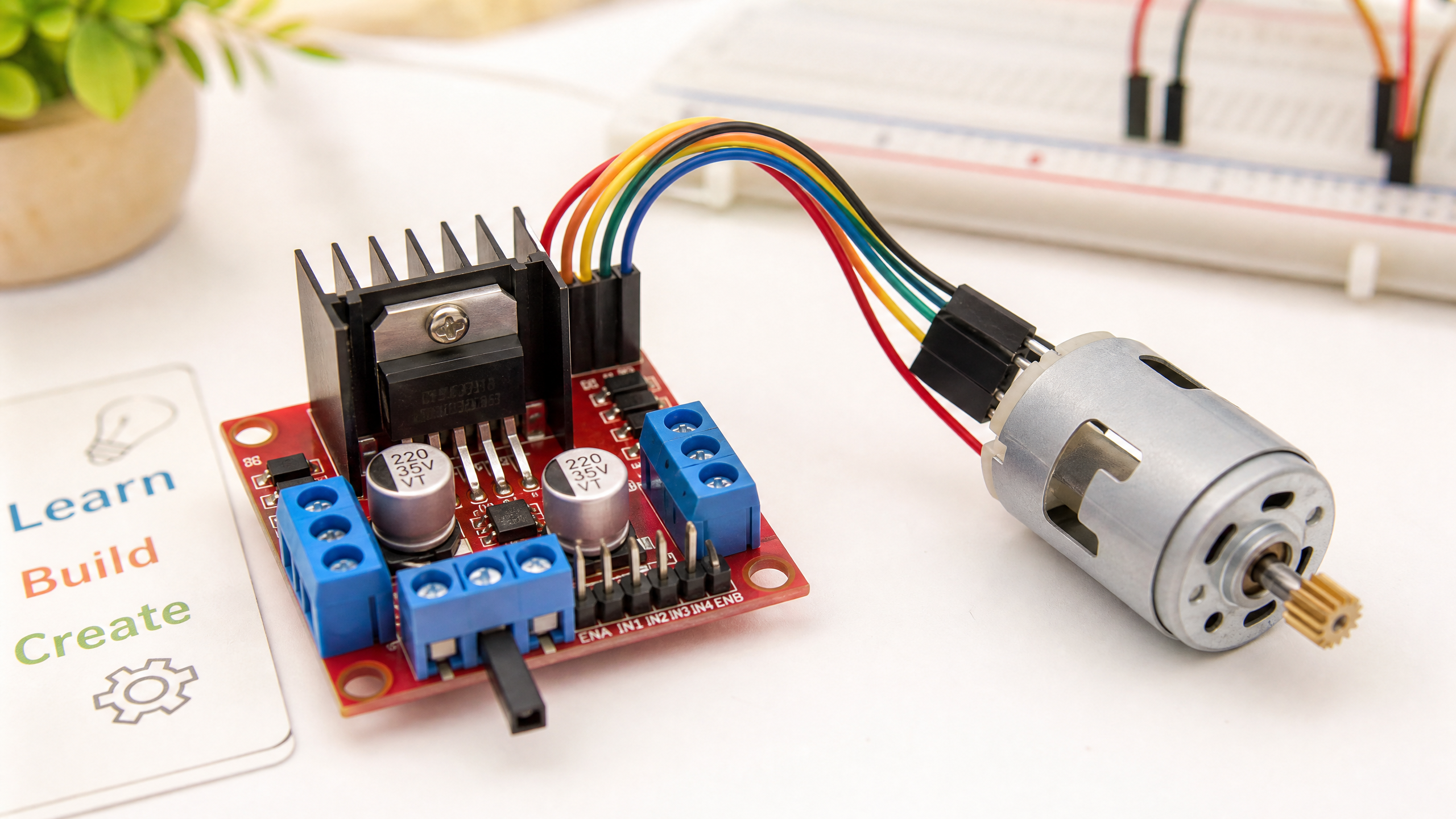
</svg>The L298N Motor Driver Module
The L298N is the most common motor driver module for beginners. It’s inexpensive (~$2–5), widely available, and can drive two DC motors (or one stepper motor) at up to 2A per channel.
Specifications:
- Input voltage: 5V–35V (motor supply)
- Logic voltage: 5V
- Max current per channel: 2A (peak 3A)
- Two independent motor channels (A and B)
Wiring the L298N
| L298N Pin | Connect to |
|---|---|
| VCC (12V) | Motor power supply (6V–12V) |
| GND | Common ground |
| 5V (logic) | Arduino 5V |
| ENA | Arduino PWM pin (e.g. pin 9) |
| IN1 | Arduino digital pin (e.g. pin 7) |
| IN2 | Arduino digital pin (e.g. pin 8) |
| OUT1, OUT2 | Motor A terminals |
Arduino Code
// L298N Motor Driver - Basic Control
const int ENA = 9;   // PWM pin for speed control
const int IN1 = 7;   // Direction control
const int IN2 = 8;   // Direction control

void setup() {
  pinMode(ENA, OUTPUT);
  pinMode(IN1, OUTPUT);
  pinMode(IN2, OUTPUT);
}

void motorForward(int speed) {
  // speed: 0–255
  digitalWrite(IN1, HIGH);
  digitalWrite(IN2, LOW);
  analogWrite(ENA, speed);
}

void motorBackward(int speed) {
  digitalWrite(IN1, LOW);
  digitalWrite(IN2, HIGH);
  analogWrite(ENA, speed);
}

void motorStop() {
  digitalWrite(IN1, LOW);
  digitalWrite(IN2, LOW);
  analogWrite(ENA, 0);
}

void loop() {
  motorForward(200);   // ~78% speed forward
  delay(2000);
  motorStop();
  delay(500);
  motorBackward(150);  // ~59% speed backward
  delay(2000);
  motorStop();
  delay(500);
}
Understanding PWM Speed Control
The analogWrite() function generates a PWM (Pulse Width Modulation) signal. Instead of a constant voltage, it rapidly switches between 0V and 5V. The ratio of on-time to off-time (the duty cycle) determines the effective voltage seen by the motor driver’s enable pin.
analogWrite(ENA, 255)→ 100% duty cycle → full speedanalogWrite(ENA, 128)→ 50% duty cycle → half speedanalogWrite(ENA, 0)→ 0% duty cycle → stopped
Common Issues
Motor doesn’t spin: Check that ENA is HIGH (or connected to 5V if you’re not using speed control). The L298N won’t drive the motor if ENA is low.
Motor spins but weakly: The L298N is built from bipolar transistors, so it drops a significant voltage across the H-bridge — roughly 2V at light load, but climbing toward 4–5V near the 2A-per-channel limit (the datasheet rates the combined saturation voltage at up to 4.9V at 2A). If your motor needs 6V, supply a few volts more (8V or higher) to the VCC pin, and more still if you’re pushing high current.
Arduino resets when motor starts: The motor is drawing too much current from the same power supply as the Arduino. Use separate power supplies for the motor and the Arduino.
Next week, we’ll look at CAN bus — a communication protocol that lets multiple microcontrollers talk to each other reliably, even in electrically noisy environments.