Setting Up CAN Bus for Robotics
CAN bus is the communication protocol that runs modern cars — and increasingly, robots. Here's what it is, why it matters, and how to set it up with two Arduinos and an MCP2515 module.
If you’ve ever wondered how the dozens of computers inside a modern car all communicate with each other, the answer is CAN bus (Controller Area Network). Originally developed by Bosch in the 1980s for automotive applications, CAN bus has become the communication backbone of choice for robotics systems that need reliable, real-time communication between multiple nodes.
Why CAN Bus?
Before CAN bus, connecting multiple microcontrollers meant a tangle of point-to-point wires. CAN bus solves this elegantly: all nodes share two wires (CAN High and CAN Low), and any node can send a message to any other node.
What makes CAN bus special:
- Differential signaling: CAN uses the voltage difference between CANH and CANL, making it highly resistant to electrical noise
- Multi-master: any node can initiate communication (unlike I2C, which has a single master)
- Priority-based arbitration: if two nodes transmit simultaneously, the higher-priority message wins without data corruption
- Built-in error detection: CRC checking, bit stuffing, and acknowledgment frames catch transmission errors automatically
- Long distances: reliable communication up to 40 meters at 1 Mbit/s, or up to 1 km at lower speeds
These properties make CAN bus ideal for robots with multiple motor controllers, sensor nodes, or any system where reliable real-time communication matters.
CAN Bus Basics
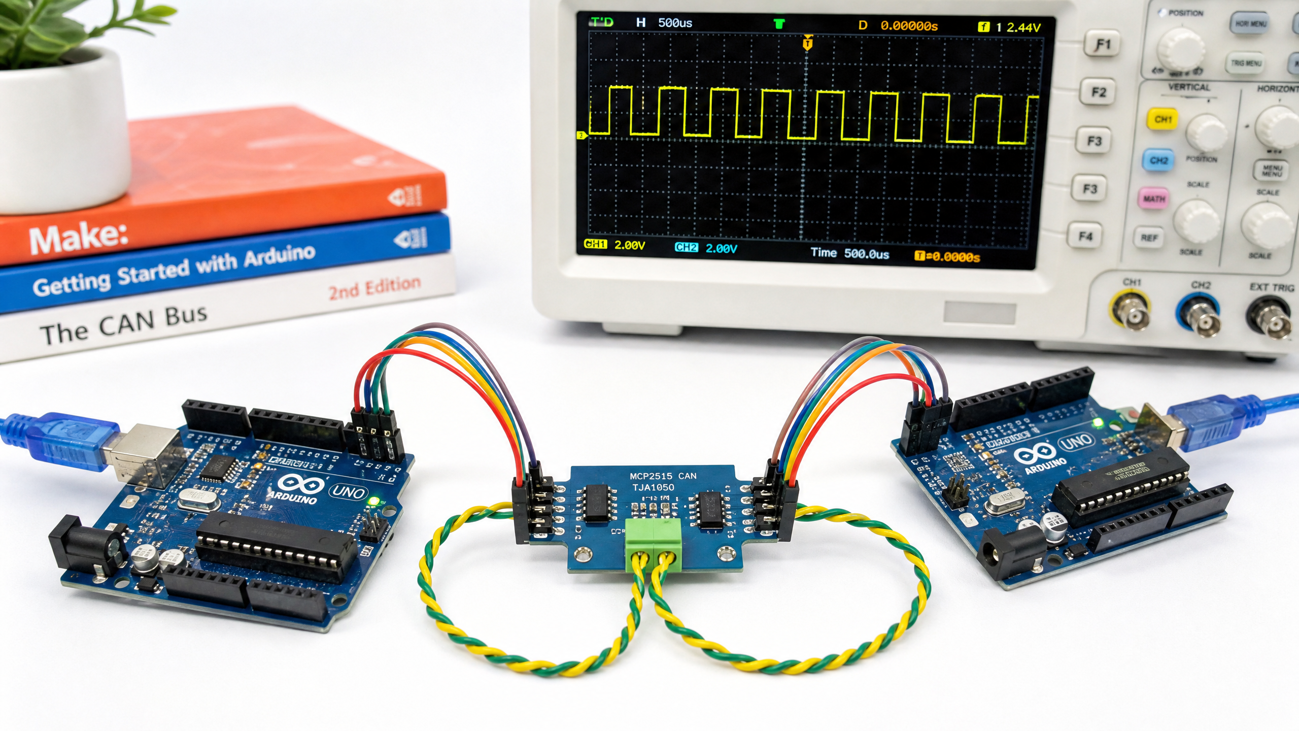
CAN bus uses two wires: CANH (CAN High) and CANL (CAN Low). In the recessive (idle) state, both wires sit at 2.5V. In the dominant (active) state, CANH rises to ~3.5V and CANL falls to ~1.5V — a 2V differential.
Termination resistors (120Ω) must be placed at both ends of the bus. Without them, signal reflections cause communication errors. Most CAN bus modules include a solder jumper to enable the termination resistor.
Hardware: MCP2515 + TJA1050
The most common way to add CAN bus to an Arduino is the MCP2515 CAN controller paired with a TJA1050 CAN transceiver. These are usually sold together on a small blue module for about $3–5.
The MCP2515 communicates with the Arduino via SPI (Serial Peripheral Interface), which we’ll cover in detail in a future tutorial.
Wiring Two Arduinos via CAN Bus
Arduino 1 (Transmitter):
| MCP2515 Pin | Arduino Pin |
|---|---|
| VCC | 5V |
| GND | GND |
| CS | Pin 10 |
| SO (MISO) | Pin 12 |
| SI (MOSI) | Pin 11 |
| SCK | Pin 13 |
| INT | Pin 2 |
Arduino 2 (Receiver): Same wiring.
Between the two MCP2515 modules:
- CANH → CANH
- CANL → CANL
- Enable termination resistors on both modules (120Ω at each end)
Installing the Library
Install the coryjfowler mcp_can library specifically via the Arduino IDE Library Manager:
Sketch > Include Library > Manage Libraries > search “mcp_can coryjfowler”
There are several forks of mcp_can in circulation, and some use a different readMsgBuf signature. The coryjfowler fork provides the 3-argument readMsgBuf(&rxId, &len, rxBuf) signature used in the code below.
Transmitter Code
#include <SPI.h>
#include <mcp_can.h>

const int SPI_CS_PIN = 10;
MCP_CAN CAN(SPI_CS_PIN);

void setup() {
  Serial.begin(115200);

  // Initialize CAN bus at 500 kbps
  while (CAN.begin(MCP_ANY, CAN_500KBPS, MCP_8MHZ) != CAN_OK) {
    Serial.println("CAN init failed, retrying...");
    delay(100);
  }

  CAN.setMode(MCP_NORMAL);
  Serial.println("CAN bus initialized!");
}

void loop() {
  // Send a message with ID 0x100, 8 bytes of data
  byte data[8] = {0x01, 0x02, 0x03, 0x04, 0x05, 0x06, 0x07, 0x08};

  if (CAN.sendMsgBuf(0x100, 0, 8, data) == CAN_OK) {
    Serial.println("Message sent!");
  } else {
    Serial.println("Send failed");
  }

  delay(500);
}
Receiver Code
#include <SPI.h>
#include <mcp_can.h>

const int SPI_CS_PIN = 10;
MCP_CAN CAN(SPI_CS_PIN);

void setup() {
  Serial.begin(115200);

  while (CAN.begin(MCP_ANY, CAN_500KBPS, MCP_8MHZ) != CAN_OK) {
    Serial.println("CAN init failed, retrying...");
    delay(100);
  }

  CAN.setMode(MCP_NORMAL);
  Serial.println("CAN bus ready, waiting for messages...");
}

void loop() {
  if (CAN_MSGAVAIL == CAN.checkReceive()) {
    long unsigned int rxId;
    unsigned char len = 0;
    unsigned char rxBuf[8];

    CAN.readMsgBuf(&rxId, &len, rxBuf);

    Serial.print("Received ID: 0x");
    Serial.print(rxId, HEX);
    Serial.print(" Data: ");
    for (int i = 0; i < len; i++) {
      Serial.print(rxBuf[i], HEX);
      Serial.print(" ");
    }
    Serial.println();
  }
}
CAN Message IDs and Priority
Every CAN message has an identifier (11-bit standard or 29-bit extended). This ID serves two purposes:
- Identification: receivers use the ID to know what the message contains
- Priority: lower ID numbers have higher priority. If two nodes transmit simultaneously, the one with the lower ID wins.
In a robot, you might assign IDs like:
0x001— Emergency stop (highest priority)0x010— Motor controller commands0x020— Sensor readings0x100— Status/telemetry (lowest priority)
Troubleshooting
“CAN init failed”: Check your SPI wiring, especially CS, MOSI, MISO, and SCK. Also verify the crystal frequency — most modules use 8 MHz, but some use 16 MHz.
Messages sent but not received: Ensure both modules have termination resistors enabled. Check that CANH connects to CANH and CANL to CANL (not crossed).
Intermittent errors: Check your power supply. CAN bus is noise-resistant, but a noisy power rail can still cause issues. Add 100nF decoupling capacitors near the VCC pins.
Next week, we’ll explore the world of robot vision — comparing 2D cameras and 3D depth cameras, and when to use each.