I2C and SPI: The Two Most Common Communication Protocols
After CAN bus, I2C and SPI are the protocols you'll use most often to connect sensors and peripherals to your microcontroller. Here's how they work and when to use each.
In robotics, you’ll constantly need to connect sensors, displays, motor drivers, and other peripherals to your microcontroller. Two protocols handle the vast majority of these connections: I2C and SPI. Understanding both will make you much more effective at building hardware.
I2C (Inter-Integrated Circuit)
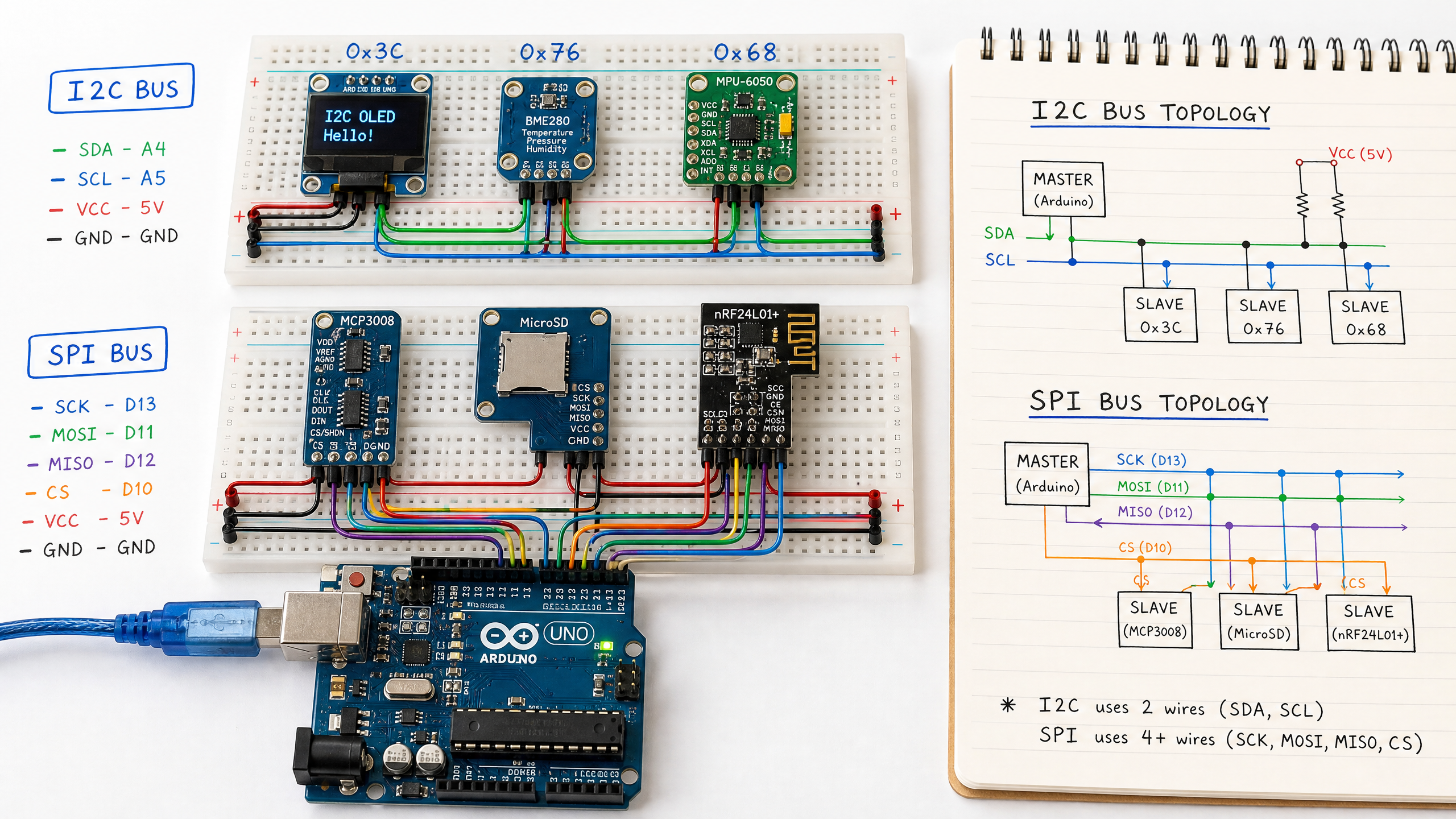
I2C uses just two wires: SDA (Serial Data) and SCL (Serial Clock). This makes it ideal for connecting many devices with minimal wiring.
Every I2C device has a unique 7-bit address (0x00–0x7F). The master (usually your Arduino) addresses a specific device before communicating with it. Up to 112 devices can share the same two wires (128 addresses minus 16 reserved).
I2C on Arduino:
- SDA → Arduino pin A4 (Uno) or pin 20 (Mega)
- SCL → Arduino pin A5 (Uno) or pin 21 (Mega)
#include <Wire.h>

void setup() {
  Wire.begin(); // Initialize as I2C master
  Serial.begin(9600);
}

void loop() {
  // Read from MPU-6050 IMU (address 0x68)
  Wire.beginTransmission(0x68);
  Wire.write(0x3B); // Starting register for accelerometer data
  Wire.endTransmission(false);
  Wire.requestFrom(0x68, 6, true); // Request 6 bytes

  int16_t ax = Wire.read() << 8 | Wire.read();
  int16_t ay = Wire.read() << 8 | Wire.read();
  int16_t az = Wire.read() << 8 | Wire.read();

  Serial.print("Accel X: "); Serial.print(ax / 16384.0);
  Serial.print(" Y: "); Serial.print(ay / 16384.0);
  Serial.print(" Z: "); Serial.println(az / 16384.0);

  delay(100);
}
I2C limitations: relatively slow (100 kHz standard, 400 kHz fast mode), and the bus can only be as long as a few meters reliably.
SPI (Serial Peripheral Interface)
SPI uses four wires: MOSI (Master Out Slave In), MISO (Master In Slave Out), SCK (Clock), and CS/SS (Chip Select). It’s faster than I2C (up to 80 MHz on some specialized high-end peripherals/MCUs) and full-duplex (can send and receive simultaneously). Note that an Arduino Uno is limited to about 8 MHz (F_CPU/2); that 80 MHz figure only applies to specialized high-end devices.
The trade-off: each SPI device needs its own CS wire. With many devices, this adds up.
SPI on Arduino Uno:
- MOSI → Pin 11
- MISO → Pin 12
- SCK → Pin 13
- CS → Any digital pin (you choose)
#include <SPI.h>

const int CS_PIN = 10;

void setup() {
  pinMode(CS_PIN, OUTPUT);
  digitalWrite(CS_PIN, HIGH); // Deselect device
  SPI.begin();
  Serial.begin(9600);
}

byte readRegister(byte reg) {
  digitalWrite(CS_PIN, LOW);  // Select device
  SPI.transfer(reg | 0x80);   // Read command (bit 7 = 1)
  byte value = SPI.transfer(0x00); // Read response
  digitalWrite(CS_PIN, HIGH); // Deselect device
  return value;
}

void loop() {
  byte whoAmI = readRegister(0x0F); // WHO_AM_I register
  Serial.print("Device ID: 0x");
  Serial.println(whoAmI, HEX);
  delay(1000);
}
I2C vs SPI: When to Use Which
| Feature | I2C | SPI |
|---|---|---|
| Wires needed | 2 (shared) | 4 + 1 per device |
| Speed | Up to 400 kHz (standard) | Up to 80 MHz |
| Multiple devices | Easy (address-based) | One CS wire per device |
| Full duplex | No | Yes |
| Common uses | Sensors, displays, EEPROMs | SD cards, ADCs, high-speed sensors |
Use I2C when you have many low-speed sensors and want to minimize wiring. Use SPI when you need high data rates (SD cards, display modules, high-speed ADCs).
Many devices support both protocols — check the datasheet.