3D Printing Robot Parts: From CAD to Physical Component
3D printing has transformed robotics by making custom parts accessible to everyone. Learn the basics of designing and printing parts for your robot.
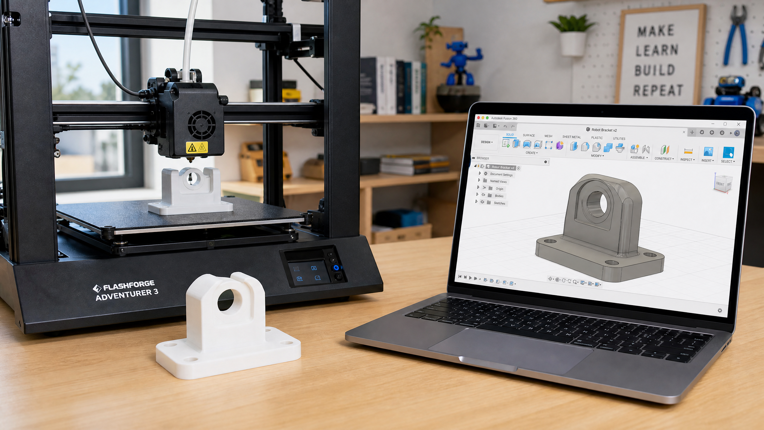
One of the most transformative tools for the modern roboticist is the 3D printer. What once required a machine shop and significant expense can now be done at home in a few hours. Custom brackets, sensor mounts, chassis parts, and enclosures are all within reach.
What to Print (and What Not To)
3D printed parts are excellent for:
- Sensor mounts and brackets
- Custom chassis and frames
- Enclosures and covers
- Spacers and standoffs
- Prototype parts you’ll later manufacture properly
3D printed parts are less suitable for:
- High-stress structural components (use aluminum or steel)
- Parts that need very tight tolerances (±0.2mm is typical for FDM)
- Parts exposed to high heat (PLA softens at ~60°C)
- Waterproof enclosures (FDM prints are porous without post-processing)
Choosing a Material
PLA (Polylactic Acid): The easiest to print. Good for prototypes and non-structural parts. Biodegradable. Softens at ~60°C — not suitable for parts near motors or in hot environments.
PETG (Polyethylene Terephthalate Glycol): Tougher than PLA, more heat-resistant (~80°C), slightly flexible. Excellent all-around choice for robot parts.
ABS (Acrylonitrile Butadiene Styrene): Strong and heat-resistant (~100°C), but difficult to print (warps, requires enclosure). Only use if you specifically need its properties.
TPU (Thermoplastic Polyurethane): Flexible rubber-like material. Great for wheels, grippers, and vibration dampeners.
Here’s the same information side by side, so you can pick at a glance:
| Material | Heat resist. | Ease of printing | Best for |
|---|---|---|---|
| PLA | ~60°C | Easiest | Prototypes, non-structural parts |
| PETG | ~80°C | Easy | All-around robot parts |
| ABS | ~100°C | Hard (warps) | Heat-exposed parts only |
| TPU | Flexible | Moderate | Wheels, grippers, dampeners |
Designing in Fusion 360
Fusion 360 is free for personal use and is the most popular CAD tool for hobby robotics. Key concepts:
- Sketch: draw 2D shapes on a plane
- Extrude: turn a 2D sketch into a 3D solid
- Fillet: round sharp edges (important for 3D printing — sharp corners stress concentrate)
- Hole: add mounting holes (use 3.2mm diameter for M3 screws to allow for printer tolerance)
Print Settings for Robot Parts
For structural parts:
- Layer height: 0.2mm (good balance of strength and speed)
- Infill: 40–60% (gyroid or honeycomb pattern)
- Perimeters/walls: 3–4 (critical for strength)
- Top/bottom layers: 4–5
For decorative parts:
- Layer height: 0.15mm (smoother surface)
- Infill: 15–20%
- Perimeters: 2
Design Tips for Better Prints
Orient for strength: FDM parts are weakest in the Z direction (between layers). Orient your part so the main load direction is along X or Y.
Add fillets: Round all sharp edges with at least 1mm radius. This reduces stress concentration and improves print quality.
Design for assembly: Add 0.2–0.3mm clearance between mating parts. What looks like a perfect fit in CAD will be too tight when printed.
Use heat-set inserts: For threaded holes that will be assembled and disassembled repeatedly, press-fit brass heat-set inserts give much stronger threads than printed plastic.