
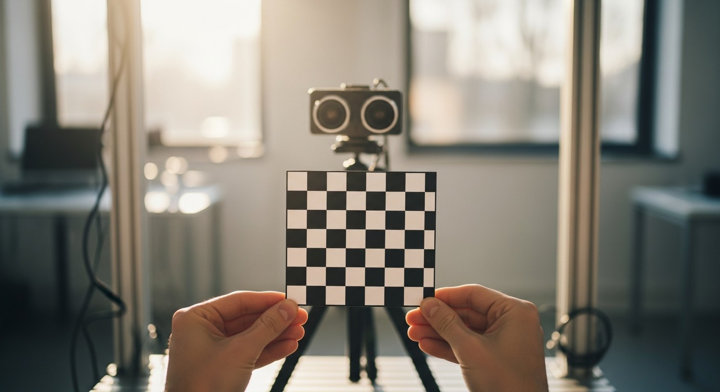
Camera Calibration & Intrinsics
A camera doesn't know its own geometry until you tell it. Learn the pinhole model, the intrinsic matrix, and how to calibrate a camera with a checkerboard — in plain OpenCV and inside ROS 2.
Last week you unpacked a point cloud — a set of real 3D coordinates, ready to use. A plain 2D camera never hands you anything that clean. It gives you a grid of pixels, and pixels alone don’t know how far away anything is, or even whether the lens bent the image on the way in. Before you can trust a camera’s output for any real measurement — how far a gripper is from a part, how big an object is, how to fuse an image with a LiDAR scan — you need to know exactly how that specific camera turns the 3D world into a 2D picture. That process is camera calibration, and its output is a small set of numbers, the intrinsics, that every vision pipeline downstream quietly depends on.
This week stays in the perception block and covers the math and the workflow: what the intrinsic matrix actually represents, why lenses distort images, and how to run a calibration yourself — both as a standalone Python script and as a ROS 2 tool.
What You’ll Learn
- The pinhole camera model: how a 3D point becomes a 2D pixel
- What the intrinsic matrix (
fx,fy,cx,cy) means, in plain terms - Why real lenses distort images, and what the distortion coefficients correct
- How to calibrate a camera with a checkerboard, in standalone OpenCV
- How to run the same calibration inside ROS 2 and wire the result into your camera driver
- The pitfalls that produce a calibration that looks fine but silently isn’t
The Pinhole Camera Model
The simplest useful model of a camera is a pinhole: light from a 3D point passes through a single infinitesimal opening and lands on a flat image plane behind it, forming an upside-down projection. Real lenses are more complex, but the pinhole model captures the one relationship that matters for calibration — how a 3D point’s position relates to where it lands in the image.
That projection is captured in one equation:
X and Z are the point’s real-world coordinates relative to the camera (in meters); u is the resulting pixel column. The Y/Z pair produces the pixel row v the same way, using fy and cy. Four numbers — fx, fy, cx, cy — fully describe this mapping, and together they’re called the intrinsic matrix, usually written K:
| Symbol | What it means |
|---|---|
fx, fy | Focal length, in pixels (not millimeters) — how strongly the lens magnifies the scene onto the sensor. Usually close but not identical, because sensor pixels aren’t always perfectly square |
cx, cy | The principal point — the pixel coordinate directly behind the lens’s optical center. Close to the image center, but rarely exact |
K | The 3×3 matrix combining all four, used by every downstream tool (OpenCV, ROS 2, MoveIt) that needs to reason about this specific camera |
Every camera — even two units of the exact same model — has its own slightly different K, because it depends on the individual sensor’s mounting and the individual lens’s manufacturing tolerances. That’s the whole reason calibration is a per-camera exercise, not a one-time lookup.
Distortion: Why Straight Lines Bend
The pinhole model assumes a perfect, infinitely small opening. Real lenses bend light more the further it is from the optical axis, which bows straight lines — like a door frame or a checkerboard edge — into gentle curves near the edges of the image. This is radial distortion, described by coefficients k1, k2, k3. A smaller, separate effect called tangential distortion (p1, p2) comes from the lens not being perfectly parallel to the sensor. Together, these five numbers — the distortion coefficients — let software straighten an image back out, a step called undistortion, which every accurate measurement from a camera depends on just as much as the intrinsic matrix does.
Calibrating with a Checkerboard
Both the intrinsic matrix and the distortion coefficients are found the same practical way: show the camera a flat pattern with precisely known geometry — a black-and-white checkerboard — from many angles, and let the math work backward from “here’s where each corner should be” to “here’s the lens model that explains where each corner actually landed.”
Print a checkerboard, measure one square’s real side length precisely (this is the only physical measurement calibration needs), and capture 15–20 photos with it tilted and shifted to different parts of the frame — corners and edges matter more than dead center. Then run something like this:
import cv2
import numpy as np
import glob

# Interior corners of your checkerboard, not the number of squares
PATTERN_SIZE = (9, 6)
SQUARE_SIZE_M = 0.025  # the real, measured side length of one square

# The known 3D layout of the checkerboard corners (flat, so Z = 0)
objp = np.zeros((PATTERN_SIZE[0] * PATTERN_SIZE[1], 3), np.float32)
objp[:, :2] = np.mgrid[0:PATTERN_SIZE[0], 0:PATTERN_SIZE[1]].T.reshape(-1, 2)
objp *= SQUARE_SIZE_M

objpoints = []  # the same known 3D layout, once per usable image
imgpoints = []  # the corners actually detected, once per usable image
criteria = (cv2.TERM_CRITERIA_EPS + cv2.TERM_CRITERIA_MAX_ITER, 30, 0.001)

for fname in glob.glob('calib_images/*.jpg'):
    img = cv2.imread(fname)
    gray = cv2.cvtColor(img, cv2.COLOR_BGR2GRAY)
    found, corners = cv2.findChessboardCorners(gray, PATTERN_SIZE, None)
    if not found:
        continue
    corners = cv2.cornerSubPix(gray, corners, (11, 11), (-1, -1), criteria)
    objpoints.append(objp)
    imgpoints.append(corners)

rms_error, K, dist_coeffs, rvecs, tvecs = cv2.calibrateCamera(
    objpoints, imgpoints, gray.shape[::-1], None, None
)
print(f'RMS reprojection error: {rms_error:.3f} px')
print('Intrinsic matrix (K):\n', K)
print('Distortion coefficients:', dist_coeffs.ravel())

np.savez('camera_calibration.npz', K=K, dist=dist_coeffs)
findChessboardCorners locates the corners to roughly a pixel; cornerSubPix then sharpens each one to sub-pixel precision, which matters a lot for calibration accuracy. calibrateCamera solves for the K matrix and distortion coefficients that best explain every detected corner across every image, and returns the RMS reprojection error — the average pixel distance between where a corner was actually detected and where the fitted model predicts it should be. Under about 0.5 pixels is a good calibration; well above 1 pixel usually means a bad image should be dropped, or more images are needed.
With K and dist_coeffs in hand, undistorting any future frame from this camera is two calls:
data = np.load('camera_calibration.npz')
K, dist_coeffs = data['K'], data['dist']

img = cv2.imread('test_frame.jpg')
h, w = img.shape[:2]
new_K, roi = cv2.getOptimalNewCameraMatrix(K, dist_coeffs, (w, h), alpha=1, newImgSize=(w, h))
undistorted = cv2.undistort(img, K, dist_coeffs, None, new_K)
alpha=1 keeps every original pixel, adding black borders where the straightened image no longer covers a rectangle; alpha=0 crops tightly instead, at the cost of losing some field of view.
Calibrating Inside ROS 2
If the camera is already a ROS 2 node publishing sensor_msgs/msg/Image, the camera_calibration package (part of image_pipeline) automates the checkerboard workflow above with a live GUI instead of a batch of saved photos:
sudo apt install ros-jazzy-camera-calibration

ros2 run camera_calibration cameracalibrator \
  --size 9x6 --square 0.025 \
  --ros-args -r image:=/camera/image_raw -p camera:=/camera
--size is the same interior-corner count as PATTERN_SIZE above, and --square the same measured side length. A window opens showing the live camera feed with four progress bars — X, Y, SIZE, SKEW — that fill in as you move the checkerboard to different positions, distances, and tilts in view. Once all four are reasonably full, the CALIBRATE button lights up; click it, wait for the solve, then SAVE to write out a tarball containing the source images and a ost.yaml calibration file with the same K and distortion coefficients your standalone script would have produced.
That YAML file is how the rest of the ROS 2 ecosystem finds out about this camera’s calibration — point your camera driver’s camera_info_url parameter at it, and it publishes the calibration alongside every image on /camera/camera_info, ready for image_proc’s rectify node or anything else downstream that needs undistorted images or accurate intrinsics.
| Standalone OpenCV script | ROS 2 camera_calibration | |
|---|---|---|
| Where it runs | Any Python environment with saved images | Inside the ROS graph, against a live topic |
| Best for | Offline calibration, non-ROS pipelines, batch datasets | Cameras already wired up as ROS 2 nodes |
| Output | Your own .npz/.yaml, however you choose to save it | ost.yaml, ready for camera_info_url |
| Feedback while shooting | None — check reprojection error after the fact | Live X/Y/SIZE/SKEW coverage bars |
Common Pitfalls
Confusing squares with interior corners. An 8×6 grid of squares has only 7×5 interior corners — and --size/PATTERN_SIZE wants the corner count. Get this wrong and detection silently fails on every image.
Barely moving the checkerboard. A calibration built from mostly front-on, centered shots fits the center of the image well and the distortion coefficients poorly, because the edges — where distortion is worst — never contributed data. Cover the corners and edges of the frame, and tilt the board, not just translate it.
Mismeasuring the square size. SQUARE_SIZE_M isn’t cosmetic — it sets the real-world scale of every rvec/tvec result and any distance you later derive from this camera. A square measured as 2.5 cm when it’s actually 2.4 cm quietly scales every downstream measurement by about 4%.
Reusing a calibration after changing focus or resolution. fx, fy, cx, cy are only valid for the exact focus setting and image resolution they were calibrated at. Refocusing the lens, or switching a driver from 720p to 1080p, invalidates the old numbers even on the same physical camera.
Skipping cornerSubPix. Corner detection alone is usually only accurate to about a pixel. For a calibration whose whole point is sub-pixel accuracy, that’s a meaningful chunk of your error budget — always refine with cornerSubPix (or let the ROS 2 tool do it for you) before fitting.
Recap
| What you want | How to do it |
|---|---|
| Model how a 3D point becomes a pixel | The pinhole equation: u = fx·(X/Z) + cx (and the v equivalent) |
| Describe a specific camera’s geometry | The intrinsic matrix K — fx, fy, cx, cy |
| Correct lens bending | Distortion coefficients k1, k2, k3, p1, p2, applied via cv2.undistort |
| Calibrate offline in Python | cv2.findChessboardCorners → cornerSubPix → cv2.calibrateCamera |
| Calibrate a live ROS 2 camera | ros2 run camera_calibration cameracalibrator --size ... --square ... |
| Use the result downstream | Point camera_info_url at the saved YAML; image_proc rectifies from there |
A calibrated camera is what turns “a grid of pixels” into “a measuring instrument” — everything from AR overlays to stereo depth to fusing a camera with a LiDAR point cloud starts with the numbers you found this week. Next week keeps building on that idea from the other direction: Sensor Fusion: IMU + Odometry (EKF), where you’ll combine two already-calibrated but individually noisy sensors into one trustworthy pose estimate.